Assembly Line
Assembly line merupakan salah
satu cara optimalisasi proses pada operasi sebuah industry. Assembly line dapat
menghemat banyak sumber daya dan waktu. Bayangkan butuh berapa banyak SDM dan
waktu yang dibutuhkan dalam proses bagaimana manufacturing dalam banyak bidang
bisa dilakukan dalam skala massal.
Pada awalnya assembly line
diterapkan oleh ford pada proses produksi mobilnya yang awalnya pembuatan
sebuah mobil memakan waktu 35 setelah menerapkan konsep assembly line setiap
mobil hanya membutuhkan waktu produksi selama 20 menit bayangkan penghematan
waktu dan sumber daya yang dilakukan. Awalnya mulanya assembly line ini
diterapkan oleh salah satu manajernya, ia mendapat inspirasi pada saat melihat
proses pemotongan hewan.
Bayangkan berapa waktu yang
dibutuhkan dalam pembutan mobil modern yang memiliki puluhan ribu part tidak
seperti mobil ford kuno yang partnya tidak begitu banyak dalam proses
produksinya. Assembly line dapat menekan biaya produksi yang dibutuhkan seingga
harga jual semakin rendah.
Assembly Line Balancing
Assembly
Line Balancing (ALB, Keseimbangan Lini Perakitan) adalah permasalahan
penyeimbangan beban pada stasiun-stasiun kerja di bagian lini perakitan.
Keseimbangan pada lini perakitan adalah sangat penting karena menentukan
seberapa besar kecepatan dan kedayagunaan (efisiensi) produksi.
Secara
deterministik, kecepatan produksi lini perakitan ditentukan oleh stasiun kerja
yang memiliki kecepatan operasi yang paling lambat (waktu operasi yang
terbesar). hal ini dikarenakan stasiun kerja yang lain harus mengalami waktu
menganggur (idle) baik menunggu material input maupun menunggu daerah WIP (work
in process) di depannya menjadi kosong. Selain itu, jika kecepatan produksi
stasiun-stasiun kerja pada lini perakitan berbeda secara signifikan, efisiensi
lini perakitan tersebut menjadi rendah. Hal ini diakibatkan waktu operasi tidak
digunakan sepenuhnya dalam mentransformasikan barang, akan tetapi ada waktu
operasi yang terbuang dikarenakan idle (menganggur).
Pada
permasalahan ini, diasumsikan ada serangkaian proses dalam lini perakitan.
Setiap proses memiliki waktu operasi yang berbeda-beda. Selain itu, ada batasan
keterdahuluan (precedence constraint) yakni sejumlah proses baru dapat
dilakukan setelah proses prasyarat -nya (predecessor) selesai. Tujuan dari
permasalahan ini adalah menentukan pengelompokan proses-proses pada lini
perakitan menjadi stasiun-stasiun kerja yang akan memaksimumkan efisiensi lini
perakitan tersebut. Terkadang, pada permasalahan ini juga dapat ditambahkan
kendala seperti jumlah maksimum stasiun kerja atau kecepatan minimum lini
perakitan (waktu operasi maksimum lini perakitan).
Henry Ford Changes the World, 1908
At the beginning of the 20th century
the automobile was a plaything for the rich. Most models were complicated
machines that required a chauffer conversant with its individual mechanical
nuances to drive it. Henry Ford was determined to build a simple, reliable and
affordable car; a car the average American worker could afford. Out of this
determination came the Model T and the assembly line - two innovations that
revolutionized American society and molded the world we live in today.
Henry Ford did not invent the car;
he produced an automobile that was within the economic reach of the average
American. While other manufacturers were content to target a market of the
well-to-do, Ford developed a design and a method of manufacture that

Henry Ford and his first car
the Quadricycle, which he
built in 1896
|
steadily reduced the cost of the
Model T. Instead of pocketing the profits; Ford lowered the price of his car.
As a result, Ford Motors sold more cars and steadily increased its earnings -
transforming the automobile from a luxury toy to a mainstay of American
society.
The Model T made its debut in 1908
with a purchase price of $825.00. Over ten thousand were sold in its first
year, establishing a new record. Four years later the price dropped to $575.00
and sales soared. By 1914, Ford could claim a 48% share of the automobile
market.
Central to Ford's ability to produce
an affordable car was the development of the assembly line that increased the
efficiency of manufacture and decreased its cost. Ford did not conceive the
concept, he perfected it. Prior to the introduction of the assembly line, cars
were individually crafted by teams of skilled workmen - a slow and expensive
procedure. The assembly line reversed the process of automobile manufacture.
Instead of workers going to the car, the car came to the worker who performed
the same task of assembly over and over again. With the introduction and
perfection of the process, Ford was able to reduce the assembly time of a Model
T from twelve and a half hours to less than six hours.
Developing the Model T
The Ford Motor Company manufactured
its first car - the Model A - in 1903. By 1906, the Model N was in production
but Ford had not yet achieved his goal of producing a simple, affordable car.
He would accomplish this with the Model T. Charles Sorensen - who had joined
Henry Ford two years earlier - describes how Ford had him set up a secret room
where design of the new car would be carried out:
"Early one morning in the
winter of 1906-7, Henry Ford dropped in at the pattern department of the
Piquette Avenue plant to see me. 'Come with me, Charlie,' he said, 'I want to
show you something.'
I followed him to the third floor
and its north end, which was not fully occupied for assembly work. He looked
about and said, 'Charlie, I'd like to have a room finished off right here in
this space. Put up a wall with a door in big enough to run a car in and out.
Get a good lock for the door, and when you're ready, we'll have Joe Galamb come
up in here. We're going to start a completely new job.'
The room he had in mind became the
maternity ward for Model T.
It took only a few days to block off
the little room on the third floor back of the Piquette Avenue plant and to set
up a few simple power tools and Joe Galamb's two blackboards. The blackboards
were a good idea. They gave a king-sized drawing which, when all initial
refinements had been made, could be photographed for two purposes: as a
protection against patent suits attempting to prove prior claim to originality
and as a substitute for blueprints. A little more than a year later Model T,
the product of that cluttered little room, was announced to the world. But
another half year passed before the first Model T was ready for what had
already become a clamorous market...
The summer before, Mr. Ford told me
to block off the experimental room for Joe Galamb, a momentous event occurred
which would affect the entire automotive industry. The first heat of vanadium
steel in the country was poured at the United Steel Company's plant in Canton,
Ohio.
Early that year we had several
visits from J. Kent Smith, a noted English metallurgist from a country which
had been in the forefront of steel development...

The 1908 Model T. Two forward
gears, a 20 horsepower engine
and no driver doors.
They sold like hot cakes
|
Ford, Wills, and I listened to him
and examined his data. We had already read about this English vanadium steel.
It had a tensile strength nearly three times that of steels we were using, but
we'd never seen it. Smith demonstrated its toughness and showed that despite
its strength it could be machined more easily than plain steel. Immediately Mr.
Ford sensed the great possibilities of this shock-resisting steel. 'Charlie,'
he said to me after Smith left, 'this means entirely new design requirements,
and we can get a better, lighter, and cheaper car as a result of it.'
It was the great common sense that
Mr. Ford could apply to new ideas and his ability to simplify seemingly
complicated problems that made him the pioneer he was. This demonstration of
vanadium steel was the deciding point for him to begin the experimental work
that resulted in Model T...
Actually it took four years and more
to develop Model T. Previous models were the guinea pigs, one might say, for
experimentation and development of a car which would realize Henry Ford's dream
of a car which anyone could afford to buy, which anyone could drive anywhere,
and which almost anyone could keep in repair. Many of the world's greatest
mechanical discoveries were accidents in the course of other experimentation.
Not so Model T, which ushered in the motor transport age and set off a chain
reaction of machine production now known as automation. All our experimentation
at Ford in the early days was toward a fixed and, then wildly fantastic goal.
By March, 1908, we were ready to
announce Model T, but not to produce it, On October 1 of that year the first
car was introduced to the public. From Joe Galamb's little room on the third
floor had come a revolutionary vehicle. In the next eighteen years, out of Piquette
Avenue, Highland Park, River Rouge, and from assembly plants all over the
United States came 15,000,000 more."
Birth of the Assembly Line
A few months later- in July 1908 -
Sorensen and a plant foreman spent their days off developing the basics of the
Assembly Line:
"What was worked out at Ford
was the practice of moving the work from one worker to another until it became
a complete unit, then arranging the flow of these units at the right time and
the right place to a moving final assembly line from which came a finished
product. Regardless of earlier uses of some of these principles, the direct
line of succession of mass production and its intensification into automation
stems directly from what we worked out at Ford Motor Company between 1908 and
1913...
As may be imagined, the job of
putting the car together was a simpler one than handling the materials that had
to be brought to

The old fashioned way - limousines are
assembled at individual stations
by a Pittsburg manufacturer, 1912
|
it. Charlie Lewis, the youngest and
most aggressive of our assembly foremen, and I tackled this problem. We
gradually worked it out by bringing up only what we termed the fast-moving
materials. The main bulky parts, like engines and axles, needed a lot of room. To
give them that space, we left the smaller, more compact, light-handling
material in a storage building on the northwest comer of the grounds. Then we
arranged with the stock department to bring up at regular hours such divisions
of material as we had marked out and packaged.
This simplification of handling
cleaned things up materially. But at best, I did not like it. It was then that
the idea occurred to me that assembly would be easier, simpler, and faster if we
moved the chassis along, beginning at one end of the plant with a frame and
adding the axles and the wheels; then moving it past the stockroom, instead of
moving the stockroom to the chassis. I had Lewis arrange the materials on the
floor so that what was needed at the start of assembly would be at that end of
the building and the other parts would be along the line as we moved the
chassis along. We spent every Sunday during July planning this. Then one Sunday
morning, after the stock was laid out in this fashion, Lewis and I and a couple
of helpers put together the first car, I'm sure, that was ever built on a
moving line.
We did this simply by putting the
frame on skids, hitching a towrope to the front end and pulling the frame along
until axles and wheels were put on. Then we rolled the chassis along in notches
to prove what could be done. While demonstrating this moving line, we worked on
some of the subassemblies, such as completing a radiator with all its hose
fittings so that we could place it very quickly on the chassis. We also did
this with the dash and mounted the steering gear and the spark coil."
Implementation
The basics of the Assembly Line had
been established but it would take another five years for the concept to be
implemented. Implementation would await construction of the new Highland Park
plant which was purpose-built to incorporate the assembly line. The process
began at the top floor of the four-story building where the engine was
assembled and progressed level by level to the ground floor where the body was
attached to the chassis.

End of the Line. The Model T's body is joined
to its chassis at the Highland Park plant
|
"By August, 1913, all links in
the chain of moving assembly lines were complete except the last and most
spectacular one - the one we had first experimented with one Sunday morning
just five years before. Again a towrope was hitched to a chassis, this time
pulled by a capstan. Each part was attached to the moving chassis in order,
from axles at the beginning to bodies at the end of the line. Some parts took
longer to attach than others; so, to keep an even pull on the towrope, there
must be differently spaced intervals between delivery of the parts along the
line. This called for patient timing and rearrangement until the flow of parts
and the speed and intervals along the assembly line meshed into a perfectly
synchronized operation throughout all stages of production. Before the end of
the year a power-driven assembly line was in operation, and New Year's saw three
more installed. Ford mass production and a new era in industrial history had
begun"
References:
Charles Sorensen's account can be found in: Sorensen,
Charles, E., My Forty Years with Ford (1956); Banum, Russ, The Ford Century
(2002); Brinkley, Douglas, Wheels for the world: Henry Ford, his company, and a
century of progress, 1903-2003 (2003).
How To Cite This Article:
"Henry Ford Changes the World, 1908," EyeWitness to History
www.eyewitnesstohistory.com (2005).
What Is Assembly Line Balancing?
Balancing an assembly line can speed
production or save money.
Some companies hire outside
consultants for assembly line balancing.
Article Details
- Written By: Jordan Weagly
- Edited By: Angela B.
- Last Modified Date: 18 August
2014
- Copyright Protected:
2003-2014 Conjecture Corporation
-
Assembly line balancing can be loosely defined as the process of
optimizing an assembly line with regard to certain factors. Configuring an
assembly line is a complicated process, and optimizing that system is an
important part of many manufacturing business models. Maintaining and operating
one is often quite costly, as well. The main focus of balancing is usually to
optimize existing or planned assembly lines to minimize costs and maximize
gains.
For instance, a car company might
want to alter its assembly line layout in order to speed production. The
company might consider the number of work stations a manufactured item must
pass before it is complete and the time required at each point. Of course, each
stage of this process requires a certain length of time, and the allotted time
to finish a process, the number of workers, or the resource demand may also be
considered, based on the specific manufacturing requirements.
The possible results of an assembly
line balancing process might be maximized efficiency, minimized time to finish
a process, or minimized number of work stations necessary within a certain time
frame. Each manufacturing process might be quite different from another, so a company
balancing unique workloads must work within the constraints and restrictions
affecting its specific assembly line.
To optimize very specific
operations, balancing an assembly line might require different methods, some of
which include equations and algorithms concerning specific aspects of the
manufacturing process. Complex manufacturing processes, such as making
automobiles in large quantities, can be broken down into smaller parts, such as
individual task times or the resource demands for each machine. This might be
especially helpful in manufacturing processes that require the consideration of
many variables, such as customized vehicles. Assembly line balancing can also
guide decision-making based on the multitude of variables that can affect the manufacturing
process.
Many times, this process might be
used as support in decision making by offering many different models and types
of data. For instance, the manager of a car manufacturer might analyze
his or her operation based on the concepts of assembly line balancing using
many different variables, and then make a decision based on that analysis.
While this might provide the best response to an optimization effort based on
one set of variables, the final decision may rest on multiple mathematical
perspectives of the same problem.
assembly line
Article Free Pass
assembly
line, industrial arrangement of
machines, equipment, and workers for continuous flow of workpieces in mass-production
operations.
The design for an assembly line is
determined by analyzing the steps necessary to manufacture each product
component as well as the final product. All movement of material is simplified,
with no cross flow, backtracking, or repetitious procedure. Work assignments,
numbers of machines, and production rates are programmed so that all operations
along the line are compatible.
An automotive
assembly line starts with a bare chassis. Components are attached successively
as the growing assemblage moves along a conveyor. Parts are matched into
subassemblies on feeder lines that intersect the main line to deliver exterior
and interior parts, engines, and other assemblies. As the units move by, each
worker along the line performs a specific task, and every part and tool is
delivered to its point of use in synchronization with the line. A number of
different assemblies are on the line simultaneously, but an intricate system of
scheduling and control ensures that the appropriate body type and colour, trim,
engine, and optional equipment arrive together to make the desired
combinations.
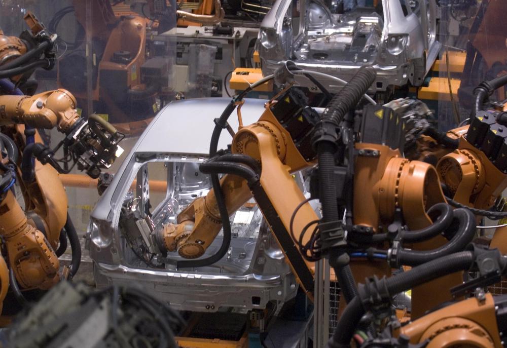
Automated
assembly lines consist entirely of machines run by machines, with little or no
human supervision. In such continuous-process industries as petroleum refining
and chemical manufacture and in many modern automobile-engine plants, assembly
lines are completely mechanized and consist almost entirely of automatic,
self-regulating equipment.
Many products, however, are still
assembled by hand because many component parts are not easily handled by
machines. Expensive and somewhat inflexible, automatic assembly machines are
economical only if they produce a high level of output. However, the
development of versatile machinery and the increased use of industrial robots
have improved the efficiency of fully automated assembly operations.
Sumber : http://www.britannica.com/EBchecked/topic/39246/assembly-line
